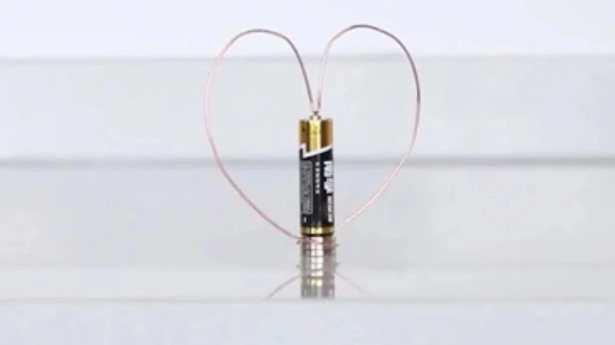
Rotating copper wireframe
Today's small production is the middle school physics review time ~ a copper wire, a battery and several magnets can form the simplest small motor:
the reason why the copper wire rotates is that the electrified wire is forced in the magnetic field. Take a square copper wire frame as an example to analyze the force:
When you choose lace back wedding dress, it will make your look glittering and amazing. Find a design that is right for you, lace back wedding dress will add new dimension to your wardrobe.
the black arrow marks the direction of the current, and the gray is the direction of the magnetic field. According to the left-hand rule, you can get the direction of the force on the lower copper wire (green arrow). The copper wire frame rotates clockwise.
the physical picture corresponding to the above picture:
of course, although the idea is very simple and easy to understand, there are still some problems in actual production. An important problem with this simple motor demonstration is that the copper wire frame actually requires a lot of debugging, to keep the copper wire in full contact with the magnet (so as to form a closed loop), and to ensure that the copper wire does not get too tight to hinder rotation. In the rotation, we often encounter the copper wire turning and falling off the positive pole of the battery. Anyway, it takes a little more patience than expected. (for reference, the diameter of the copper wire I use is 1.2mm)
another problem to note is that this too simple motor design can cause the battery to heat up. It's not a big problem to show briefly, but it's not suitable to turn on the circuit for a long time. If you feel the battery getting hot, stop and dry it